
News & Events
Omnetics Winter 2019 Newsletter


Latching Micro-D and Nano-D Connectors
 Latching Micro-D and Nano-D connectors from Omnetics employ a squeeze-latch system that offers significant advantages in making quick cable connections to mating connectors and panel equipment. In addition to being very small and lightweight, our latching connectors are available at both 25 and 50 mils. (one thousands of an inch) spacing.
They have passed extensive  shock and vibration testing, including pull testing that exceeds 100 pounds of pull force. The new push-and-latch design significantly reduces the time and effort required to plug a Micro-D or Nano-D connector into a circuit. It eliminates the use of screwdrivers and hand tools.
Applications we have served include portable electronic modules and instruments used in a wide range of rugged applications. Unmanned vehicles, optical surveillance, and flight deck test equipment require quick connect and disconnect methods not readily available before in a rectangular-shaped connection systems. Medical devices, such as surgery tools, ultrasound monitors, and imaging scopes require frequent connection and removal from instrument panels.
 Panel-mounted latching connectors offer options for connecting front panels to inside instrumentation, including P.C. board lead frames and direct wiring. These highly rugged connectors with their compact designs are built with aluminum alloy 6061 shells plated with nickel (other materials are available). Contact counts range from 9 to 51 positions.
The connectors use a one-piece beryllium copper flex pin design, plated with nickel/gold for robust service that operates from -55 degrees to +125 degrees C. Wired connectors include 26 AWG Teflon® insulated copper wire that provides up to 3 amps per line on Micro sizes and offer 30 and 32 AWG wiring for the Nano sized connectors. A wide range of wire count and cables can be designed into custom back-shells for long-range ruggedized service. Cable systems include braided shields to reduce electromagnetic interference (EMI) and cross talk.
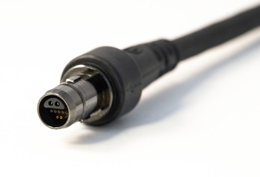
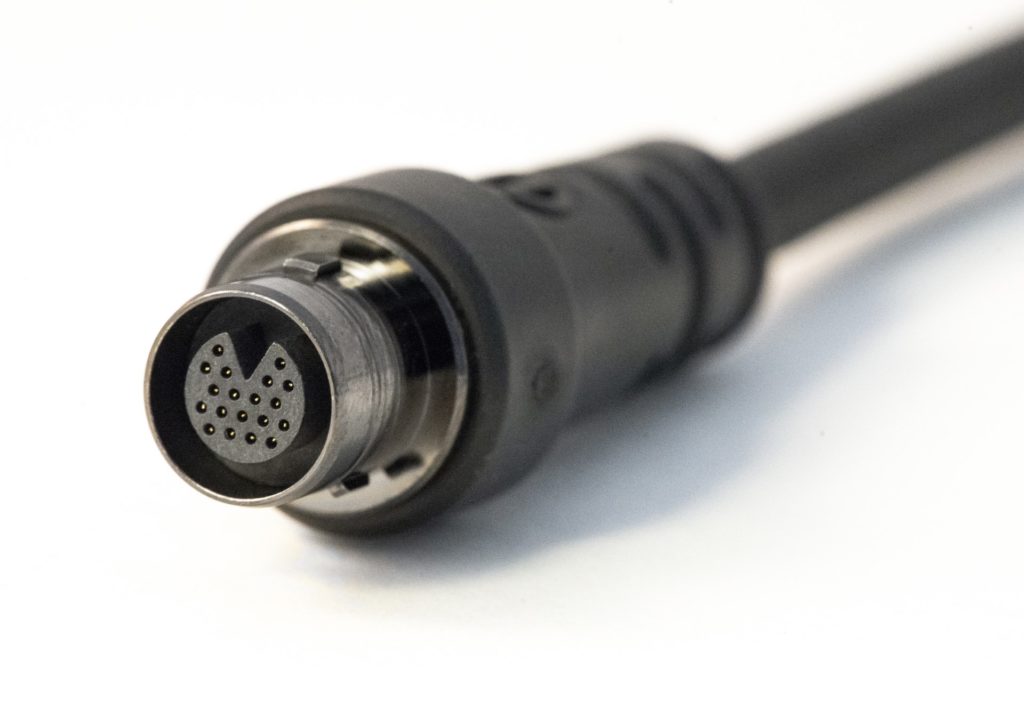
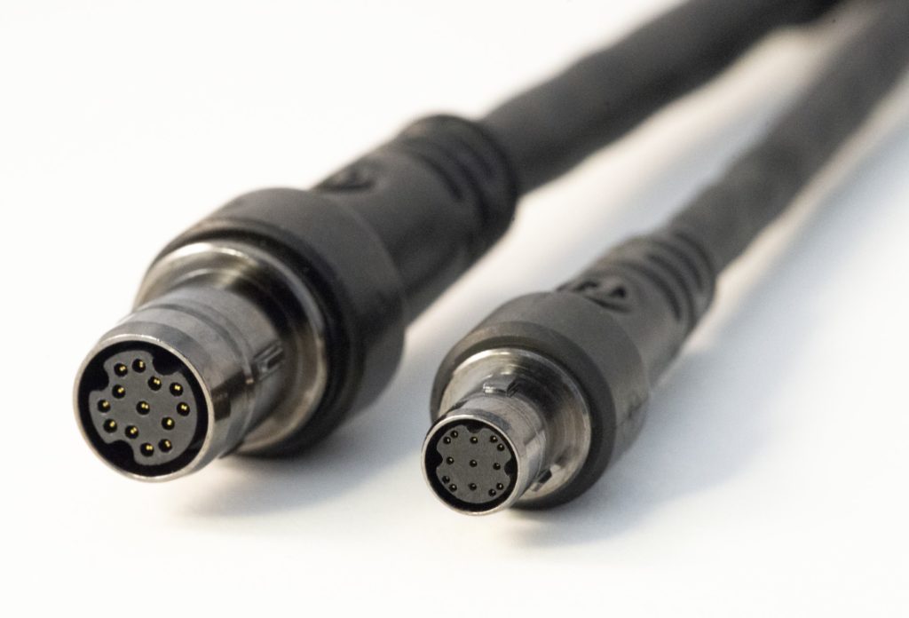
Digital signals, such as the HDMI Nano-latch connector shown, optical surveillance systems, and low-voltage differential signals are applying these quick-change connectors in their systems. The latching Micro-D and Nano-D family has years of solid reliable experience in the field and has saved a lot of connection and disconnection time.
From the Engineer’s Desk: High Speed Connector Design
What is Coax?
by Ryan Satrom, Signal Integrity Engineer
The coax connector industry is worth over $2 billion per year (Connector Supplier). They are used in communication devices, wireless applications, satellites, audio, and video. Nearly all markets utilize coax connectors, from military to medical to aerospace. There are similarities to other connector styles, but there are also aspects that set coax connectors apart. This is the first in a series of articles that are aimed at helping readers better understand coax connectors – what they are, why they are used, and current offerings from Omnetics.

Figure 1. Layers of a coax cable.
Coax, short for co-axial, literally means “joint/mutual axis”. In the case of coax connectors, there are typically four layers that all share the same axis and center point.
- Signal: Typically a solid wire, though stranded wire can be used for certain applications.
- Insulator: A material with a low dielectric constant (εR) that allows for high-frequency signal transmission.
- Shield: The shield has two primary purposes: (1) carry the ground currents for the coax signal, and (2) block all signals from the outside world. The shield generally consists of a foil, a braid, or both. It is designed with 100% coverage so that the coax signal is fully isolated. This can be achieved due to what is called “skin effect”.
- Jacket: Provides protection for the cable.

Figure 2. Current distribution of a coax signal at high frequency.
Skin effect is a phenomenon that describes how signals travel at high frequency where they will seek not only the path of least resistance but also the path of least inductance. As frequencies increase, current distribution (Figure 2, red) will both move further to the outside of the conductor and move as close as possible to the opposite-travelling current. This pushes all currents on the shield to the inside portion of the shield, ensuring that no current exists on the outside of the shield, and thus no signal will radiate to create EMI.
The co-axial construction is designed to better address the following two needs of high-frequency signals:
- Characteristic Impedance: As frequencies increase, the characteristic impedance of the coax becomes critical. The impedance is determined primarily by the diameter of the signal conductor, the OD of the insulator, and the dielectric constant of the insulation material.
- Excellent Shielding: The outer shield fully surrounds the signal conductor, yielding nearly perfect coverage.
In future articles, we will look in-depth at coax, including impedance, the purpose of coax contacts, and their strengths and weaknesses. These articles will provide a deeper understanding of the uses for coax and will assist engineers in selecting the correct coax connector with confidence. A description of the coax offerings at Omnetics will be included.
Did you know?
NASA’s Opportunity rover has  officially been on Mars for 15 years! It was designed to operate for 90 Martian days, but completed over 5,000 Martian days on the red planet as of February 2018. Although NASA is currently unable to communicate with Opportunity due to a dust storm in June, Opportunity has given NASA the chance to expand their discovery of space and Mars.(NASA)
Omnetics’ Nano connectors are used on space missions for their small size and extreme durability. More information on our connectors for space is available.